Andy Howes
2005-01-09 21:49:09 UTC
Can anyone guide me on how to wire up a RELCO device to my two rail layout
please.
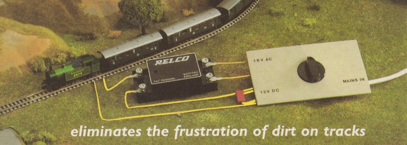
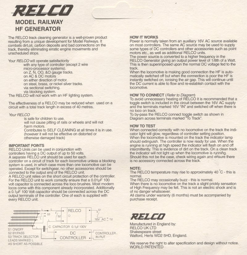
I have a RELCO, which when laid on the table has to the left, 2 terminals
plus the words 'OUT' & 'TO TRACK'. On the right are 2 terminals and the
words 'TO CONTROLLER' & '16V IN'. I also have a capacitor.
The track is PECO Setrack and the power supply is by wiring soldered
directly to the 'fishplate'.
Please take me from there ?
Andy
please.
I have a RELCO, which when laid on the table has to the left, 2 terminals
plus the words 'OUT' & 'TO TRACK'. On the right are 2 terminals and the
words 'TO CONTROLLER' & '16V IN'. I also have a capacitor.
The track is PECO Setrack and the power supply is by wiring soldered
directly to the 'fishplate'.
Please take me from there ?
Andy